UltraVision Touch
KEY FEATURES
Guided Probe Positioning
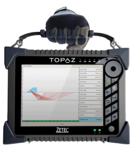
- With UltraVision Touch, you can virtually position the probes on the specimen to ensure maximum volumetric coverage. The inspector is guided through these processes by the user-friendly menu, which displays multiple views of the proposed inspection in one Scanplan type image

Calculation of all TOFD and UT parameters
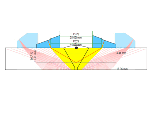
- Advanced TOFD calculator will calculate:
- Probe Center Separation (PCS)
- Front Wedges Spacing (FWS)
- The dead zones and locus
- These are presented as a ray tracing image where the operator can make manual adjustments. All the UT parameters will then be calculated so that the user can begin immediate scanning
Overview of total inspection coverage
- The Advanced Calculator provides an overview of the inspection coverage achieved by all the different channels (groups) used in a setting. This is particularly valuable when a Scanplan combines phased array and TOFD

Optimized layout for calibration
- The advanced processing features of the UltraVision Touch calibration provide optimized layouts to facilitate phased array calibration for sensitivity, wedge delay, Time Corrected Gain (TCG) and velocity for each angle
Calibration status for all channels
- Before acquisition begins, UltraVision Touch displays the calibration status for all channels (groups). If the relevant symbol on the display is not in green, this indicates that the related parameter has not been calibrated. Only when all symbols are green can scanning and data acquisition begin
TOFD Analysis Tools
- Parabolic cursors allow precise sizing and this information is logged automatically in the table of indications
- Lateral Wave Synchronization tool
- Latera Wave Removal
- SAFT
Phased array Analysis
- Weld Overlay display
- Volumetric Merge
- Polar Views
Reporting
- Wide range of reports available
- Customizable templates
- User fields in reports
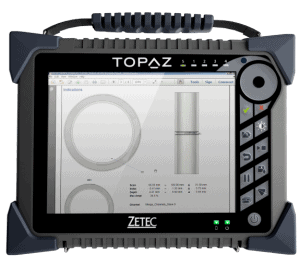
- Computer generated specimen drawings displaying the different indications on the specimen


